UNDERGROUND UTILITY DETECTION
Map what lies below before work begins
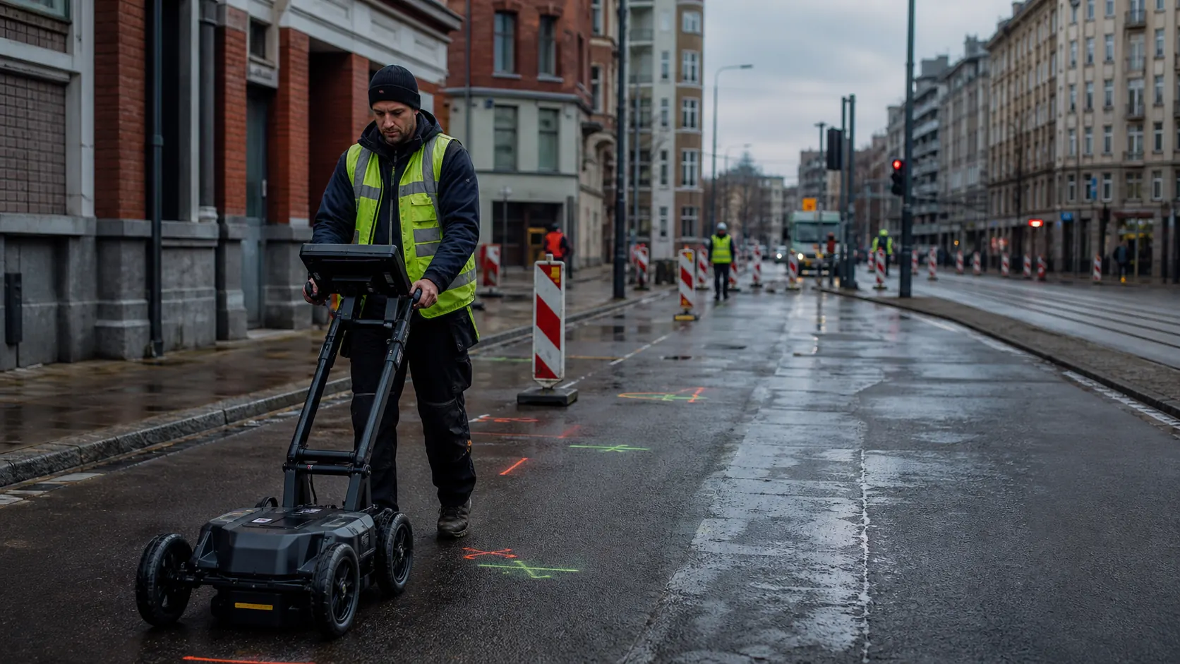
Integrated GPR, electromagnetic locating and survey positioning can create a clearer field record of buried services—supporting safer excavation, better design and more accountable infrastructure work.
RECORDS ARE A STARTING POINT
Build a current picture from multiple sources
Historic plans may be incomplete, abandoned services may remain in the ground and construction changes may never reach the record. A professional detection programme combines available documentation, site evidence, complementary sensors, positioning and verification.
Survey-grade mapping
Road and rail projects
Civil engineering
Reconstruction
CAD and BIM delivery
CURRENT PLATFORM EXAMPLE
Leica DSX utility detection solution
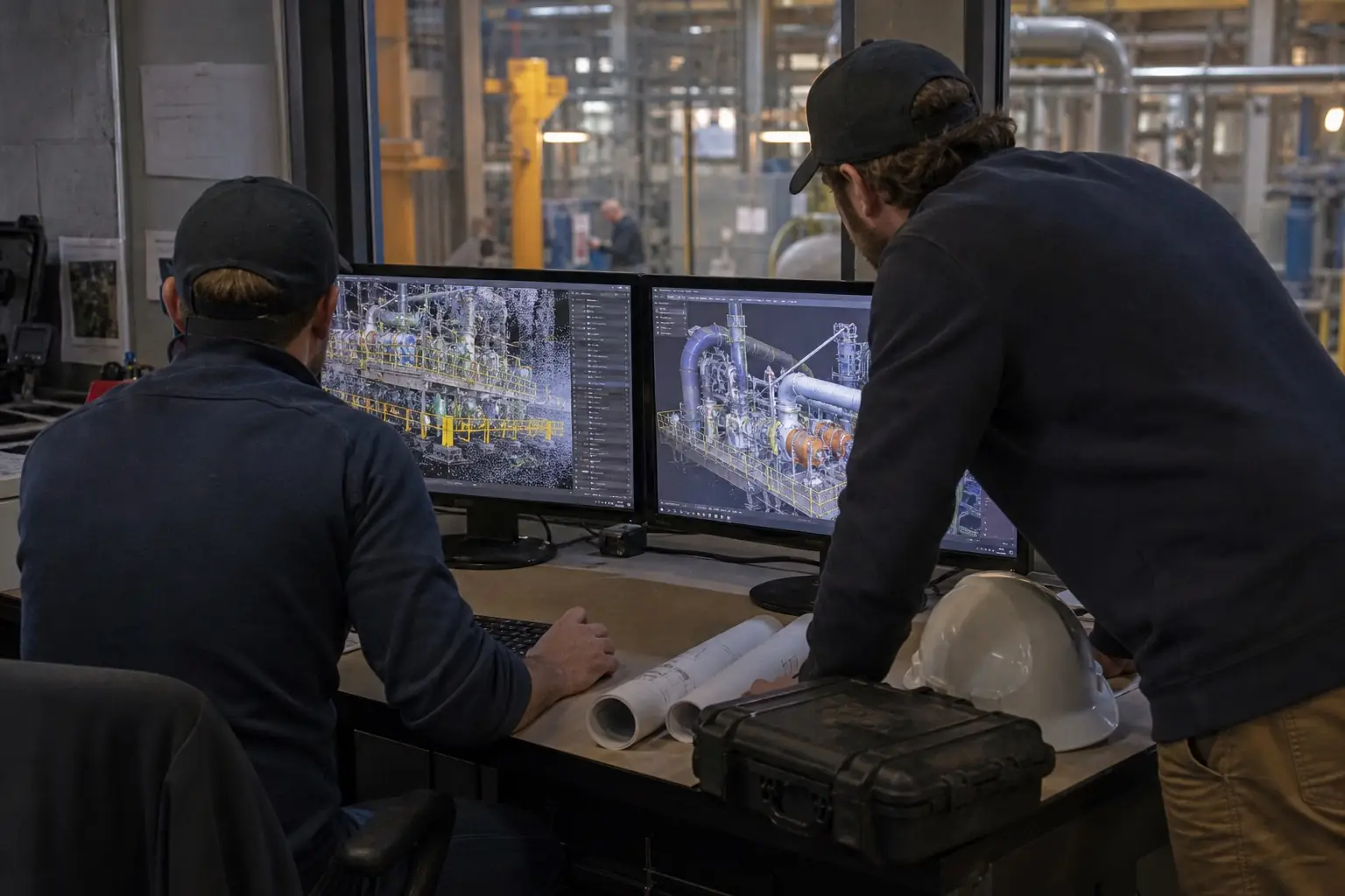
Leica DSX combines a portable ground-penetrating radar platform with DXplore field software to support guided data collection, interpretation and three-dimensional utility mapping. GNSS or total-station positioning can connect detected features to the project coordinate system.
- Guided grid acquisition and field visualisation
- GPR evidence for conductive and non-conductive utilities
- Integration with electromagnetic locating and existing records
- Georeferenced 2D and 3D utility mapping
- Export for CAD, BIM, survey and machine-control workflows
COMPLEMENTARY METHODS
No single instrument identifies every buried service
Ground conditions, depth, target material, diameter, orientation, surface access and nearby structures all affect detection. Combining evidence reduces uncertainty and creates a more defensible map.
Records and site review
Collect plans, owner information, visible chambers, cabinets, trenches, reinstatement lines and other points of interest before scanning.
EML and GPR
Use electromagnetic locating for conductive services and sondes, then GPR to add non-conductive targets, depth context and anomalies.
Position and verify
Survey detected alignments, document confidence and limitations, and use controlled exposure or other verification where the work requires certainty.
PROJECT APPLICATIONS
Better subsurface information before design and excavation
Roads, rail and public realm
Map services along streets, tram corridors, stations and transport projects before drainage, foundations, track, poles or utility diversions are designed.
Construction and excavation
Support permit-to-dig and pre-construction planning with current field evidence, marked alignments and a documented confidence level.
Utility maintenance
Locate and map water, drainage, power, communications and other networks during repair, connection, renewal and asset-record improvement.
Recovery and reconstruction
Create a usable subsurface baseline where records are fragmented and multiple infrastructure programmes must coordinate in the same corridor.
DELIVERY MODEL
Four stages to a usable utility record
Scope
Define the work area, service types, purpose, coordinate system, accuracy expectation and deliverables.
Collect
Review records and site evidence, then acquire EML, GPR and survey observations using a controlled field method.
Interpret
Correlate responses, classify confidence, map alignments and document anomalies and limitations.
Deliver
Provide marked-out information, reports, coordinates, CAD/BIM data or web-ready records for the project team.
DISCUSS A UTILITY-MAPPING PROJECT
Tell us where work is planned—and what must be located
Share the country, site type, approximate area or corridor length, available records, surface conditions, coordinate system, required outputs and timeline. TS2 Space will help define an appropriate detection and mapping workflow.
Equipment availability, configuration, permitted use and delivery depend on destination, local requirements and the agreed project scope. Detection performance, acceptance criteria and commercial terms are confirmed individually.


